In discussions on solid-state frequency converters, mention was made of an inverter used to create the 400 Hz output frequency. Here, we will describe in layman’s terms how an inverter works.
First, we begin with a direct current (DC) source of power. This can be a battery or the output of an AC to DC rectifier. It can also be the output from solar panels or any device that outputs DC.
For this discussion, let us use a 12-Volt car battery.
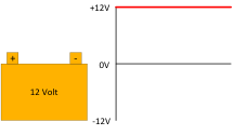
The battery produces 12 volts between its terminals. In standard automotive convention, the negative (-) terminal is connected to the chassis and the positive (+) terminal goes through a switch to the lights, radio, etc. There is no alternating current (AC). To make AC, we use an inverter.
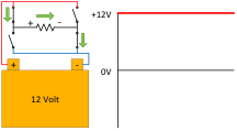
For our example, we will make a simple inverter out of four switches. In the first scene, the switches are configured with two “on” and two “off.” Each pair is along a diagonal line.
The figure above shows the top left and bottom right switch closed. The positive terminal is connected to the left side of the load.
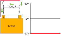
This figure shows the top right and bottom left switches closed. Positive is on the right side of the load and current is reversed.
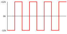
If the switches reversed back and forth 60 times a second, a 60 Hz AC square wave would be produced.


