Many times I’m asked to explain a technical statement to a person who is either non-technical or from a different branch of technology. One such question stemmed from a general comment regarding inverter sizing. The inverter is the group of switching devices that convert DC into AC.
In the next two figures, DC on the top and bottom rails can create current in two different directions by turning on or off different switches.
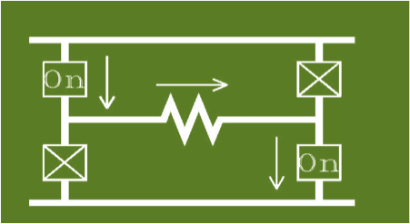
Figure 1, Current left to right

Figure 2, Current right to left
Depending how fast the switches are alternated, the current will alternate at the same frequency.
Each switch carries the full-load amperage while it is on. The 4 switches in the previous figures make up a single-phase inverter; adding 2 more switches make a 3-phase inverter.
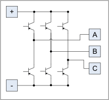
Think of this as a 3-cylinder engine. Each pair of switches connected to a phase alternates between top and bottom (+ and -).
The timing between cylinders (phases) is such that each one is 1/3 of a revolution (120°) after the next, Atop turns on, 120° later Btop and 120° later Ctop. See below.
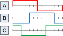
The actual timing is: Atop, Cbottom, Btop, Abottom, Ctop, Bbottom and back to Atop.
This is a very simple 3-phase inverter.