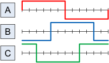
Last time, I presented an example of a simple 3-phase inverter. An analogy was made to a 3-cylinder engine. (One cylinder per phase)
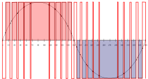
Using Pulse Width Modulation (PWM), each phase can appear to be more than the simple on/off which was shown in the timing chart.
By switching on and off very quickly, a series of gradually increasing and decreasing pulses can be created per phase. This makes the output more sinusoidal.
One limiting factor to consider from last time is that, “each switch carries the full-load amperage while it is on.”
Technically, there is a limit as to how large of a switching transistor is available from the manufacturers. One might think this limits the size of available inverters and frequency converters.
Think back to the 3-cylinder engine analogy. Imagine the limit on switching transistors to be a limit on cylinder size. How can we increase the engine size if the cylinders are as large as they can be? YES – add more cylinders.
At FCX Systems, on large inverters and converters, we shift out of the PWM mode and utilize the simple inverter model. By using 4 of the three phase inverters we create what works as a 12-cylinder engine. That creates more power and smoother output.
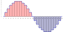
Power capability is 4 times that of a PWM single inverter. Shifting the timing of the inverters allows the creation of incremental steps in voltage. This is referred to as step wave modulation.
There is also a belief that the voltage increments create less transients and stress on windings and cables. This may prolong the life of the unit, while also providing higher power capabilities.
Normal recommendations are for the PWM design in ratings of 180 KVA and below. Above that level, the step wave design is preferred and available up to 2 MVA.


