Category: News

An old, retired machinist went back to his former place of work many years later to take a tour of the plant. The tour guide had each participant give a brief introduction and was delighted to learn the old man was a former employee. The guide took great pride in showing the new state-of-the-art computer-driven machines. Part of the description was the amazing tolerance they were able to achieve.

“This machine is accurate to a tolerance of one, one-hundred-thousandth of an inch,” the guide stated proudly. “Bet you didn’t hold tolerances to that level back in your day?” he asked the old man.

“No,” said the old machinist, “we didn’t have those kind of tolerances. We just made parts that fit exactly.”

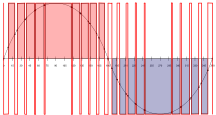
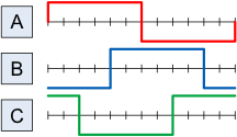
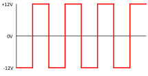
The world of electronics prior to the digital revolution was an analog world. Control and feedback voltages had an infinite number of values, and the system came into the desired setpoint exactly. Waveforms were smooth and variables were infinitely variable.

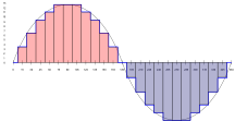
I’ll jump over the 4-bit digital beginnings and jump right in at 8 bits. Eight bits of binary looks like 01100011. The lowest value is 00000000 (0 decimal) and the highest is 11111111 (255 decimal); that’s 256 different values. It also looks like 256 steps. Each step is 1 / 256 away from the next.

For example if 11111111 (255) is 5 volts maximum and 00000000 (0) is 0 volts, then we have 0.01953125 volts per step. That can also be viewed as 0.390625% per step.

A setpoint can be 01111110, (126), 2.4609375 volts or 01111111, (127), 2.48046875 volts, but NOT 2.475 volts.

Everything becomes jittery. Yes, you can increase the bit count 16, 32, 64, etc., which reduces the error, but you still have to rely on alternating between a bit too low and a bit too high. Nothing fits exactly.

The good news is that the digital revolution brought computers and programming. Now, instead of making a machine that only does one thing, the programming can be modified to change the process without redesigning and building a new machine.

An update of software can eliminate old problems, add new algorithms and give new life to an old design. This is marvelous. It is like liquid electronics. No need to create a new circuit board, just change how it processes inputs and scales outputs.

Forget changing resistors to set the gain of amplifiers, program a new gain. Wow, this digital stuff is great! We can make the changes on a computer, plug in a cable and update the old design with a new one. What time we can save!

What did you say about jitter? I didn’t notice any jitter.

Last time, I presented an example of a simple 3-phase inverter. An analogy was made to a 3-cylinder engine. (One cylinder per phase)

Using Pulse Width Modulation (PWM), each phase can appear to be more than the simple on/off which was shown in the timing chart.

blog5-1

By switching on and off very quickly, a series of gradually increasing and decreasing pulses can be created per phase. This makes the output more sinusoidal.

blog5-2

One limiting factor to consider from last time is that, “each switch carries the full-load amperage while it is on.”

Technically, there is a limit as to how large of a switching transistor is available from the manufacturers. One might think this limits the size of available inverters and frequency converters.

Think back to the 3-cylinder engine analogy. Imagine the limit on switching transistors to be a limit on cylinder size. How can we increase the engine size if the cylinders are as large as they can be? YES – add more cylinders.

At FCX Systems, on large inverters and converters, we shift out of the PWM mode and utilize the simple inverter model. By using 4 of the three phase inverters we create what works as a 12-cylinder engine. That creates more power and smoother output.

Power capability is 4 times that of a PWM single inverter. Shifting the timing of the inverters allows the creation of incremental steps in voltage. This is referred to as step wave modulation.

blog5-3

There is also a belief that the voltage increments create less transients and stress on windings and cables. This may prolong the life of the unit, while also providing higher power capabilities.

Normal recommendations are for the PWM design in ratings of 180 KVA and below. Above that level, the step wave design is preferred and available up to 2 MVA.

Many times I’m asked to explain a technical statement to a person who is either non-technical or from a different branch of technology. One such question stemmed from a general comment regarding inverter sizing. The inverter is the group of switching devices that convert DC into AC.

In the next two figures, DC on the top and bottom rails can create current in two different directions by turning on or off different switches.

blog4-1
Figure 1, Current left to right

blog4-2

Figure 2, Current right to left

Depending how fast the switches are alternated, the current will alternate at the same frequency.

Each switch carries the full-load amperage while it is on. The 4 switches in the previous figures make up a single-phase inverter; adding 2 more switches make a 3-phase inverter.

blog4-3

Think of this as a 3-cylinder engine. Each pair of switches connected to a phase alternates between top and bottom (+ and -).

The timing between cylinders (phases) is such that each one is 1/3 of a revolution (120°) after the next, Atop turns on, 120° later Btop and 120° later Ctop. See below.

blog4-4

The actual timing is: Atop, Cbottom, Btop, Abottom, Ctop, Bbottom and back to Atop.

This is a very simple 3-phase inverter.

In discussions on solid-state frequency converters, mention was made of an inverter used to create the 400 Hz output frequency. Here, we will describe in layman’s terms how an inverter works.

First, we begin with a direct current (DC) source of power. This can be a battery or the output of an AC to DC rectifier. It can also be the output from solar panels or any device that outputs DC.

For this discussion, let us use a 12-Volt car battery.

blog3-1

The battery produces 12 volts between its terminals. In standard automotive convention, the negative (-) terminal is connected to the chassis and the positive (+) terminal goes through a switch to the lights, radio, etc. There is no alternating current (AC). To make AC, we use an inverter.

For our example, we will make a simple inverter out of four switches. In the first scene, the switches are configured with two “on” and two “off.” Each pair is along a diagonal line.

blog3-2

The figure above shows the top left and bottom right switch closed. The positive terminal is connected to the left side of the load.

blog3-3

This figure shows the top right and bottom left switches closed. Positive is on the right side of the load and current is reversed.

blog3-4

If the switches reversed back and forth 60 times a second, a 60 Hz AC square wave would be produced.

Last time, we discussed why the utilities supply 50 or 60 cycle (Hz) power and the aviation industry operates on 400 Hz power.

Obviously, the two systems are not compatible. 400 Hz is 6-2/3 times faster than 60 Hz and 8 times faster than 50 Hz. The speed of motors (and clocks) would be multiplied by the same factor. Also, a few things would just catch fire. However, we need a source of 400 Hz at the airfield so that aircraft can shut down their engines. The engines and internal generators burn fuel, create noise and produce undesired emissions.

The simplest approach would be to build a 400 Hz generator driven by an engine on the ground next to an airplane. But that would consume fuel, create noise and produce undesired emissions just like the aircraft. It would be a solution if no other power was available. However, usually utility power is not far away. The boarding bridge, hangar or other building will be using 50 or 60 Hz utility power.

But, didn’t we just say the two power systems were not compatible?

Yes, we cannot connect the two systems directly but there are ways of converting utility power to 400 Hz aviation power.

One way is to use a motor connected to the utility as the engine to drive a generator producing 400 Hz. This creates what is called a Motor Generator frequency converter, or “MG Set.” Electrical power to the motor generates horsepower out. The horsepower into the generator creates electrical power out. The engineering of the system ensures that the utility 50 or 60 Hz is correct for the motor and that the generator produces the proper voltage and 400 Hz frequency for the aircraft.

Although the MG Set solution is rather simple, it has a couple of drawbacks. First it is mechanical. The rotating parts require continuous lubrication. The air-cooling of the motor and generator create high ambient noise. Finally, because the efficiency of the MG Set is not good for normal and low loads, (50-70%) the operating power expense can be high.

A preferred method of frequency conversion is a Solid-State Frequency Converter (SSFC).

The solid-state design also takes power directly from the utility and converts it to a form acceptable to aircraft and military 400 Hz power systems.

The front end of the SSFC rectifies the utility power and creates a direct current (DC) voltage. DC is a steady voltage that does not have a significant frequency component.

The DC is then switched by power transistors to create an alternating current (AC) waveform at the required frequency of 400 HZ. The efficiency of the SSFC is quite high at all loads; typically approaching 91-94%.

Although both types of frequency converter cost about the same, the solid-state frequency converter design and provide a significantly lower operating cost when compared to MG Sets. Fuel power engine generator sets may be the only choice if utility power is not available.

The idea of making electricity useful for commercial lighting and motors initiated an argument. One side wanted direct current (DC). One wire will always be positive (+) and the other wire is always negative (-).

The other side supported alternating current (AC). In this system, the voltage is constantly moving between positive and negative. The shape of this changing voltage is a sine wave.

blog1

The changing AC voltage provided the advantage of using transformers to change the voltage. High voltage at low amps could be sent long distances over small wire, and then transformed to a safe lower voltage for distribution inside a home or factory.

Once the decision was made to use AC, the next question was, how fast should the voltage change? How many cycles per second (Hertz, Hz) should be produced?

As the frequency of the voltage change was made slower, the size and weight of the transformers and generators increased and became more expensive. As the frequency was made faster, more power was lost in the transmission lines, which also increased cost.

The most economical frequency for the power company was around 60 cycles per second. Some countries standardized on 50 cycles per second or Hertz (Hz).

When aviation began using electricity, it was DC power. As AC became more prevalent in aircraft, the primary concern was the size and weight of transformers, motors and power supplies. The idea was proposed to use a higher frequency to make the components lighter, since the length of power transmission was small, the increased power loss would be negligent.

A special generator was designed to create an output of 400 Hz. This allowed a motor which was the size of a watermelon to be replaced by one the size of a one-pound coffee can which could do the same work.

The saving of weight allowed increased cargo capacity and decreased fuel consumption. Power at 400 Hz for aviation was a success and became the standard of modern AC-powered aircraft.

Airports all around the world standardized on the same power system. This included the physical plug and cable as well as the 400 Hz power so that aircraft from anywhere in the world could land and be serviced wherever they landed.
The aviation power system of 400 Hz became one of the first worldwide-adopted standards.

Supplying 400 Hz Ground Power to the World’s Largest Marine Corps Facility

Recently, FCX commissioned 16 solid-state frequency converters in the U.S. Marine Corps’ newest MV-22 Osprey Hangar located at MCAS New River in North Carolina.

The Haskell Company, who FCX worked with on this project from start to finish, was the general contractor. It took four years for the design-build state-of-the-art facility to construct the project and has been affectionately named the “Mega Hangar” by U.S. Marines

The Mega Hangar is now the world’s largest Marine Corps facility. FCX is proud to support the U.S. Marines with supplying the 400 Hz ground power in this new Mega Hangar.

In the past few years, FCX has installed MV-22 Osprey 400 Hz ground power in several hangars at MCAS Miramar, California, new hangers at Camp Pendleton, California and MCAS Kaneohe Bay, Hawaii, and a previous hangar at MCAS New River.
MV-22 Mega Hangar

In 2008, a large floating dry dock – containing motor loads for cranes, capstans, ballast pumps and fire pumps – was transported to the Grand Bahama Shipyard. The dry dock required 50 Hz power, while the Bahamas utilizes 60 Hz power.

To supply the 50 Hz power needed for the dry dock, two 1000 KVA Caterpillar diesel generators were required. A solid-state frequency converter running off the utility solved this problem.

The second challenge was designing, building and testing a solid-state frequency converter that was rated 2000 KVA and was capable of operating large inductive loads.

FCX engineered the converter to use low frequency-switching to reduce losses. An input voltage of 12.7 KV and an output voltage of 20 KV helped reduce wire costs between the converter and the dry dock.

Two units were manufactured by FCX and the dry dock was electrically divided down the middle. At that time, the dual units comprised the world’s largest solid-state frequency converter.

The two 2000 KVA units may be paralleled at a future date.

111